Cognex Support Hub
In-Sight L38 Fixturing and Coordinate Transformation in 2D and 3D
How to use fixturing and coordinate transformation in 2D and 3D.
11/03/2025
How to use fixturing and coordinate transformation in 2D and 3D.
The In-Sight L38 has fixturing functions such as 2D PatMaxRedLine and 3D PatMax3D. Both output results in a left-handed world coordinate system.
2D Fixturing → 3D Tools: The output values of FindPatMaxRedLine in the In-Sight L38 are in millimeters and in the world coordinate system. The XY rotation angle values can be directly used in 3D tools. Since the processing time of PatMax3D is longer than 2D, it is effective when improving the overall job processing speed. The XY rotation values in the 2D image plane can be obtained and used as reference points in the 3D region.
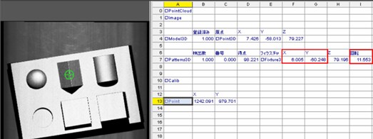
2D Fixturing → 2D Tools: When positioning with TrainPatMaxRedLine, FindPatMaxRedLine, or other 2D fixturing functions, X, Y, Z, and rotation angles can be obtained as shown in [Fig. 1] (in millimeters, world coordinate system).
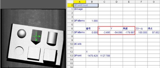
【Fig.1】
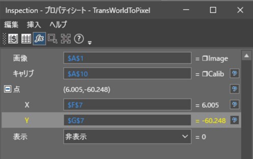
Coordinate correction → Calibration → When referencing the A1 Image cell in ExtractCalibration, the calibration structure □Calib is returned. Next, in Coordinate correction → Calibration → TransWorldToPixel, referencing the A1 cell and this A10 □Calib, and referencing the X, Y cells of the 2D fixturing result at the "point" shown in [Fig. 2], the X, Y values converted from millimeter units to pixel units are displayed as shown in row 13 of [Figure 1]. (B13, C13)
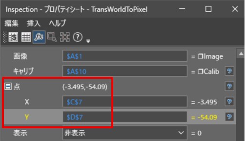
【Fig.2】
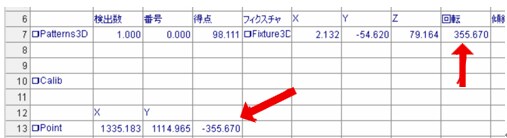
The rotation angle needs to be multiplied by -1 for coordinate transformation between left-handed and right-handed systems. [Fig. 3] shows the result of multiplying the value obtained as the angle in cell E7 of FindPatMaxRedLine in [Fig.1] by -1 in cell D13 next to cells B and C in row 13 of [Fig.1].
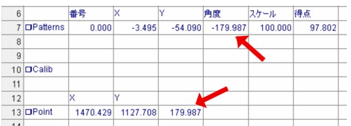
【Fig.3】
These values of XY and rotation angle converted to pixel coordinate system in B13, C13, and D13 can be used as fixturing for 2D tools such as DetectBlobs and Region in pixel units. As a reference, [Fig.4] shows an example of displaying text on the image in cell A1 using screen display → graphics → PlotString. For the image in cell A1, the display position of the string needs to be indicated in pixel units of X and Y. Since the values in cells C7 and D7 of [Fig.1] output by FindPatMaxRedLine are in millimeters, it is necessary to specify B13 and C13, which have been converted to pixel units, to determine the display position. By using the X and Y converted to pixel units, the text "Find Object" is displayed in the correct position on the image.
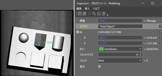
【Fig.4】
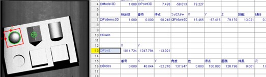
3D Fixturing → 2D Tools: When positioning using FindPatMax3D or other 3D fixturing functions, values such as X, Y, Z, and rotation angle are obtained as shown in [Fig. 5]. The units of X, Y, Z are millimeters in the world coordinate system.
【Fig.5】
Similar to 2D fixturing, referencing the A1 Image cell in ExtractCalibration returns the calibration structure □Calib. Next, in Coordinate correction → Calibration → TransWorldToPixel, referencing the A1 cell and this A10 □Calib, and referencing the X, Y cells of the 3D fixturing result at the "point" shown in [Fig.6], the X, Y values converted to pixel units are output as shown in row 13 of [Fig.5]. (B13, C13)
【Fig.6】
The rotation angle needs to be multiplied by -1 for coordinate transformation between left-handed and right-handed systems. [Fig.7] shows the result of multiplying the value obtained as the rotation in cell I7 of FindPatMax3D in [Figure 1] by -1 in cell D13 next to cells B and C in row 13 of [Fig.5].
These values of XY and rotation angle converted to pixel coordinate system in B13, C13, and D13 can be used as fixturing for 2D tools such as DetectBlobs and Region.
As a reference, [Fig.8] shows the result of using DetectBlob (cell A16) after coordinate transformation of the 3D fixturing result using the above method. It can be seen that the specified region is correctly tracked on the 2D image in response to changes in the workpiece position.
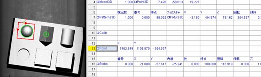
【Fig.8】
Note: Fixturing of 2D tools by using 3D fixturing can only be performed if all movements are on the XY plane.
If you want to convert from pixel coordinate system to world coordinate system, you can use the TransPixeltoWorld tool.